
For people of culture who have never specialized in electricity, even if you read the introductory book to study the circuit of switching power supply, it is not clear. The actual power supply circuit also uses new electronic components, so it is different from the explanation in the technical book.
I would like to explain the circuit of the switching power supply with the familiar TDK-Lambda “ZWS100B-5”. It is not perfect because there is no circuit diagram of the power supply, but you can understand the rough operation of the switching power supply in block units from the actual product. If you know this much, you can talk to a technician.
Switching Power Supply Circuit
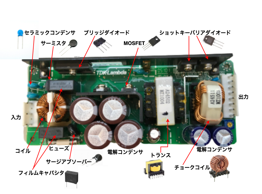
I took a picture of ZWS100B-5.
A brief explanation of the circuit is as follows: “Input from the input connector at the left end of the power supply, ① via the filter circuit and ② inrush current prevention circuit, ③ rectified and smoothed current, ④ switch and send to the transformer. The output is rectified and smoothed. ”This is the general flow of this circuit.
Let’s take a closer look.
Filter Circuit
After inputting, first enter the filter circuit consisting of a film capacitor (film capacitor) and a coil. The film capacitor is a part of the black case in the photo, and it is a capacitor with a plastic film dielectric sandwiched between the internal electrodes.
The role of the filter circuit is to suppress noise coming in from the outside and noise (noise terminal voltage) going out from the power supply side to the input side. In particular, the noise terminal voltage is important and may have adverse effects such as malfunction on other devices and devices, and there are international standards. The coil is called a common mode choke coil.
Next to the film capacitor is a black component surge absorber (varistor). A surge absorber is a component that protects electronic devices from surge voltages such as lightning. Since the resistance value changes depending on the voltage, it is possible to protect elements such as ICs from static electricity and electronic devices from lightning surges.
The mechanism is that when a high voltage is applied to the surge absorber, the resistance value drops and current flows through the surge absorber. When a current flows, the resistance value of the circuit drops and the voltage drops. As a result, the voltage applied to electronic components such as ICs can be reduced.
Inrush Current Prevention Circuit
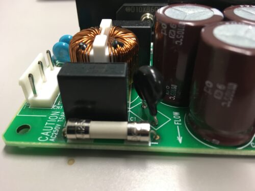
There was a 5A fuse after the filter circuit. This glass tube fuse is inexpensive and is often used as a component of electronic circuits. You can see that the fuse is blown from the outside, but this type has a protective seal wrapped around it to prevent debris from scattering around when the glass tube breaks.
When the fuse blows, the fuse is replaced, but in the case of a switching power supply, the fuse blow is rarely the primary cause, and most of the secondary blows are caused by the failure of peripheral parts. Peripheral parts are also broken, so you only need to replace the fuse
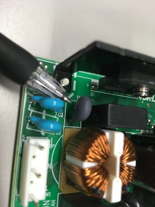
Inrush current flows when an electrolytic capacitor is on the circuit. If a surge current flows, the fuse will blow or the electrolytic capacitor will be overloaded, shortening its life. The inrush current can be suppressed with a thermistor. The gray part pointed with the pen in the photo above is the thermistor. It is also called an NTC thermistor.

As shown in the figure above, the thermistor has a high resistance value when the temperature is low, and when the temperature rises, the resistance value instantly drops to 0Ω. (The resistance value of the surge absorber changes with voltage, but the resistance value of the thermistor changes with temperature.)
The thermistor acts as a resistor when the temperature at power-on is low, and when current flows out, the resistance value drops and it becomes almost the same state as when there is no resistor. When a fixed resistor is used, heat loss always occurs, but the thermistor has almost no heat loss and efficiency is improved.