


Those who have studied electric circuits can understand circuit diagrams, but for those who do not, circuit diagrams are a big wall. Since we are not designing here, we will explain the switching power supply by dividing it into rough blocks.
Switching power supply circuit block


The switching power supply first has a “line filter” that attenuates noise and an “inrush current prevention circuit” that suppresses inrush current, and an “rectifying / smoothing circuit” converts alternating current to direct current. DC voltage that is still unstable is switched (ON / OFF) at high speed with a transistor or MOSFET to form a high-frequency pulse, and a current is passed through a “high-frequency transformer.” A rectifier diode and a smoothing capacitor are used in the subsequent stage of the transformer, the output voltage is detected and compared by the “detection circuit”, and the electric signal is fed back to the switching section by the “control circuit” to control the pulse width and control the output voltage. Make it constant.
Line Filter


The common mode choke coil acts as a noise filter that attenuates the noise that flows in from the input side and the noise that returns from the inside of the power supply to the input side.
Inrush current prevention circuit
It reduces the surge current that flows into the smoothing capacitor when the input is turned on. If the electrolytic capacitor is input when it is not charged, the current will flow at once, and it will be charged and the voltage will rise and the current value will drop. The inrush current value is determined by the capacity of the smoothing capacitor.
By inserting a resistor in the input line, the inrush current (surge current) will be 15A at maximum AC100V input and 30A at AC200V input. However, the method of suppressing the inrush current with a resistor always causes heat loss in the resistor when the power supply is operating, so it can only be used with a small capacity power supply of 100W to 150W


For power supplies with larger capacities, a thermistor is used to reduce the inrush current. In the thermistor method, the resistance value is large when the thermistor is low temperature, so the inrush current is suppressed, and then when the thermistor becomes high temperature, the resistance value becomes small, so the loss (heat) can be reduced.
Rectifying / smoothing part
Rectified with a bridge diode
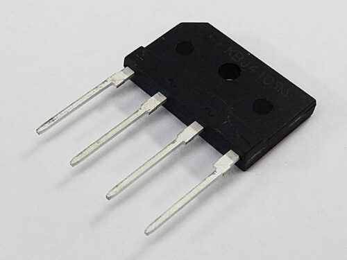

The bridge diode uses four diodes to convert alternating current to direct current (full-wave rectification).
For example, when the current flows from ① to ⑧ from the AC power supply, the current flows from ④ to ⑤ in ④⑤ on the way.


Next, when the AC power supply flows in the opposite direction, the current should flow from ⑤ to ④ in ④⑤, but the bridge diode causes the current to flow from ④ to ⑤, Next, when the AC power supply flows in the opposite direction, the current should flow from ⑤ to ④ in ④⑤, but the bridge diode causes the current to flow from ④ to ⑤, in other words, the direction in which alternating current flows can be the same (direct current).


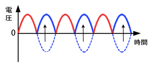
With this bridge diode, the direction of the current is changed to the solid blue line by tilting the dotted blue line in the figure below to the opposite side (full-wave rectification). Although the direction of the current has changed to direct current, the voltage fluctuation remains large at this rate.

Smooth with a smoothing capacitor


If the voltage drops too much, use an aluminum electrolytic capacitor to make the voltage “smooth”. Since the electrolytic capacitor can store electricity, it is possible to prevent the voltage from dropping by discharging the part where the input voltage drops. The pink part is the part that prevents the voltage from dropping due to the discharge of the capacitor. The reason for using an aluminum electrolytic capacitor is that it requires a certain amount of capacity because it charges and discharges.


Switching part
The rectified and smoothed direct current is turned ON / OFF by a transistor or MOS-FET to make a high frequency pulse. Both transistors and MOSFETs can be used in the sense of switching (ON / OFF), but when the capacitance increases, two transistors are used, but one MOSFET is sufficient.
The image of the high frequency pulse looks like this.


Trance
The upper high frequency pulse voltage is stepped down by a transformer.


Suppose that the input core has N1 wires wound around it, and the output core has N2 wires wound around it.
When a voltage of V1 (V) and a current of I1 (A) are passed from the input side, a current flows through the lead wire on the input side in the direction of the red arrow.
Then, according to the right-handed screw rule, a magnetic field (magnetic field) is generated downward in the core on the input side.
The magnetic field changes because the input side switches to flow or stop the current. As the magnetic field changes, a magnetic field in the opposite direction (upward) to this magnetic field is generated in the core on the output side, and an induced current flows on the output side.
V2 / V1 = N2 / N1Also, according to the law of conservation of energy, the power on the input side (voltage x current) and the power on the output side are the same.
V1 x I1 = V2 x I2
Control circuit
The control IC changes the ON / OFF time of the transistor and MOS-FET to control the output voltage constantly.
When the voltage is low, the ON time is lengthened, and when the voltage is high, the ON time is shortened.
Electronic components mounted on switching power supplies
Many electronic components are used in switching power supplies. Even if you cannot design a circuit, you can understand the power supply circuit block if you understand the part names and roles.
The explanation is based on the electronic components mounted on the 100W board-type power supply.


- Bridge diode (rectifier diode): A module that packages four diodes into one to convert AC waveform to DC full-wave rectification.
- Varistor: Used to protect elements such as ICs from static electricity and lightning surges by utilizing the characteristic that the resistance value changes depending on the voltage.
- Ceramic capacitor (capacitor): An electronic component that stores and discharges electricity (electric charge).
- X-capacitor (capacitor): It is a role to reduce the normal mode noise of the noise terminal voltage by connecting between the phases (between lines) of the power supply line and short-circuiting the lines at high frequency.
- Choke coil (inductor): Selects and removes only the common mode component that is the source of radiation noise.
- MOSFET: Abbreviation for Metal-Oxide-Semiconductor Field Effect Transistor, which translates as “metal oxide semiconductor field effect transistor”. The voltage is controlled by switching with this MOSFET.

- Photocoupler: An IC package containing an LED and a light receiving element (photodiode). When a current is passed through the LED, the light receiving element turns on. The LED and the light receiving element are electrically isolated.