
Switching power supply output
Output power is the value obtained by multiplying the output voltage (V) and the output current (A). The power supply for 5V10A is 50W, and the power supply for 24V4A is 96W.
Output power (W) = Output voltage (V) x Output current (A)
Normally, power supplies with the same rated output power (W) have the same capacity, but in reality, the current value (output power) that can be passed differs depending on the ambient temperature of the power supply. This is because the power (current value) that can be output for each ambient temperature is determined for each power source, more specifically for each output voltage, and for each placement.
The ratio of the power that can be output to the rated output power is called the load factor (derating rate), and the derating table is published in the manufacturer’s catalog or HP as “specification standard” or “instruction manual”. The “ambient temperature” here is not the room temperature but the ambient temperature of the power supply inside the device, and is often specified as room temperature + 15 ° C.
Load factor (%) = output power (W) ÷ rated output power (W) x 100
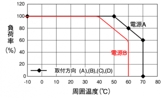
For example, suppose you have 100W power supplies A and B. Both power supplies A and B can output 24V 4.2A at the same 100W. The derating of power supply A is shown by the black line graph, and the power supply B is shown by the red line graph.
Both power supplies A and B can be used at 100% from an ambient temperature of 0 to 40 ° C, but power supply A can be used at 100% at an ambient temperature of 50 ° C, while power supply B is 80% and power supply A is 80 at an ambient temperature of 60 ° C. Power supply B can be used up to 60%, and power supply A can be used up to 60% at an ambient temperature of 70 ° C, but power supply B cannot be used.
In other words, when the ambient temperature of the power supply reaches close to 50 ° C, power supply A can be used as it is as a 100W power supply, but power supply B becomes a power supply of 80W. Power supply B will have to use the above capacity of 150W.
Also, since power supply B slides 10 ° C to the left of power supply A, it can be said that the temperature is 10 ° C higher than power supply A. Considering Arrhenius’s law of double speed at 10 ℃, power supply B has half the life of power supply A. Actually, the circuit method and parts used are different, so I can’t say it simply, but it is a guide to some extent.
Life of switching power supply
Strictly speaking, there are four life parts of switching power supplies, “photocoupler”, “relay”, “fuse”, and “solder joint” in addition to “aluminum electrolytic capacitor” and “fan”.
The photocoupler has a life due to deterioration over time due to the ambient temperature and CTR (ratio of output current to input current), and the relay has a life if it is turned on and off 100,000 times.
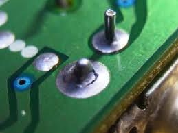
Since the thermal expansion coefficient of the printed circuit board and the electronic component are different in the solder life, stress is applied to the “solder” at the joint, and circular cracks occur around the reed. There is a difference between a double-sided board and a single-sided board, but it does not occur at the level of several years. The symptom is that there are many temporary output stops, and some of the solder cracks are connected. When vibration is applied, it outputs and stops. After that state continues for a while, the output stops completely. This is a problem that tends to occur in places where the power is turned on and off many times a day or where the temperature fluctuates greatly.
Since the glass tube fuse is also a copper wire, it may be said that it has it, but since it must be blown when a current exceeding the specified value flows, the fuse manufacturer generally recommends 10 years as the recommended replacement period.
The power supply has the above life parts, but in general, the aluminum electrolytic capacitor is the shortest life part of the switching power supply.
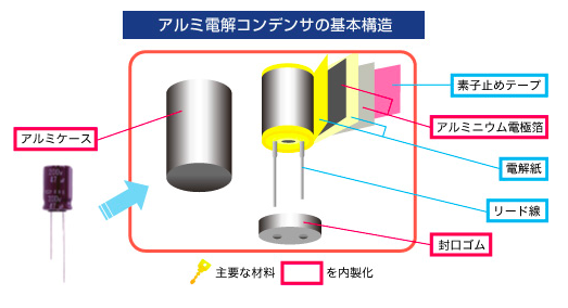
Aluminum electrolytic capacitors are made by impregnating electrolytic paper with electrolyte and putting it in a case together with lead wires.
Source: Structure of aluminum electrolytic capacitor / Nippon Chemi-Con Co., Ltd.
The life mechanism of aluminum electrolytic capacitors is as follows.
- The electrolyte inside the aluminum electrolytic capacitor gradually evaporates to the outside.
- Decrease in capacitance, increase in ESR (resistance value)
- Electrolyte expansion due to self-heating, promotion of transpiration speed
- Electrolyte dry-up
- Open state
The life of an aluminum electrolytic capacitor is defined as when the electrolyte is reduced by 20% from the beginning. The capacity of the electrolyte is called capacitance and is expressed in μF units. Even if the electrolyte drops by 20%, the ripple of the electrolytic capacitor alone will increase slightly, and there will be almost no effect on the power supply. If you continue to use it, it will eventually dry up and open, and the power output will stop. What percentage does not meet the specifications of the power supply varies depending on the power supply and the location of the electrolytic capacitor. However, the electrolyte will decrease at an accelerating rate after it decreases by 20%, so replace it at this time or replace the power supply with a new one.
The life of an electrolytic capacitor is determined by the load factor (derating rate) and ambient temperature. Several to ten or more electrolytic capacitors are used in the power supply, and the electrolytic capacitor with the shortest life is the life of the power supply. Also, the shortest electric capacitor may change depending on how the power is placed.
In the first place, the life of electrolytic capacitors is listed in the catalog as the L0 value by the electric capacitor manufacturer. Generally, a guarantee of 105 ° C and 5,000H is common. It means that the case temperature of the electrolytic capacitor can be used up to 105 ° C and is guaranteed for 5,000 hours.
5,000 hours has a life of only about half a year in continuous operation, but this is the life when the case temperature of the electrolytic capacitor is 105 ° C. Some products have a long life of L0 = 10,000 hours, but it is difficult to install standard products because there are few models and the price is high and the delivery time is long.
It is not uncommon for the board temperature to rise to 100 ° C if no measures are taken, and it is the know-how of power supply manufacturers how to dissipate this temperature and reduce it to a temperature that does not affect electrolytic capacitors and other electronic components.
Normally, electrolytic capacitors (case temperature) are used at about 70 ° C, so if the temperature drops from 105 ° C to 30 ° C, the life will be extended by 2 to the 3rd power = 8 times. In other words, 5,000 hours will extend the life to 40,000 hours (4.5 years).
Some manufacturers publish the calculated lifespan of this electrolytic capacitor on HP, while others do not.