
Rectifying・Smoothing Circuit
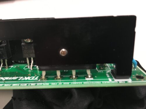
After the inrush current prevention circuit, it becomes a rectifying・smoothing circuit. The four-legged part in the photo above is a bridge diode, which dissipates heat to the black aluminum fins due to the high temperature. The larger the aluminum fins, the greater the heat dissipation effect, but in terms of cost and shape, select efficient parts (small heat loss) in order to make the fins as small as possible.
The role of the bridge diode is to convert the AC voltage AC to the DC voltage DC. Even though it is a direct current, it is a full-wave rectification that only tilts the negative part of the alternating current upward.
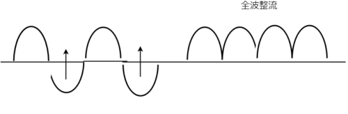
After rectifying with a bridge diode, smooth with an electrolytic capacitor. This power supply uses four 250V 180μF electrolytic capacitors to smooth the full-wave rectified voltage waveform to as straight a DC as possible. When the input is AC100V, the AC voltage waveform is a sine wave with a peak of 141V, but the output voltage after smoothing with an electrolytic capacitor is DC141V.
In addition, electrolytic capacitors store and release power, so even if the input voltage drops, 20mS can maintain the output voltage. Looking at the data of ZWS100B-5, if the load is 20%, it is possible to take a holding time of 200mS (0.2S), which is 10 times as much.
Step Down With A Transformer
The direct current through the electrolytic capacitor goes to the MOSFET and the transformer. The transformer can convert (step down) from a high voltage to a low voltage. When the MOSFET on the primary side of the transformer turns ON / OFF (switching), the current flowing on the primary side of the transformer flows or stops to adjust the voltage. As the current changes, magnetic flux is generated in the iron core on the primary side of the transformer, and its direction also changes. As a result, a voltage is generated on the secondary side of the transformer at the same time as the magnetic flux in the direction opposite to the primary side. The voltage on the primary side and the voltage on the secondary side are each proportional to the turns ratio of the transformer.
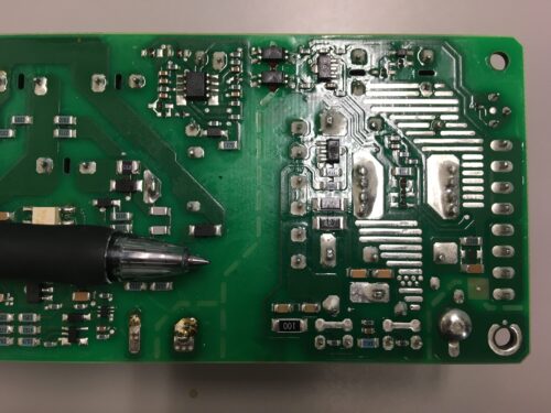
In addition to transforming the voltage, the transformer also has the role of electrically insulating. Looking at the back of the board, there is a gap of about 1 cm between the primary side and the secondary side of the transformer, and there is no circuit here.
There is a MOSFET on the secondary side of the transformer and it is used in two parallels for rectification. Subsequent electrolytic capacitors smooth the rectified voltage.
Beyond that, there is a choke coil (inductor) that connects to the output connector.